首先是了解学习ps/2 protocol,找了几份资料,简单阅读了下,天真的以为既然鼠标默认会进入流模式(stream model),我要做的只是接收数据就好了,写好代码下载后发现根本没数据送我,只是在插入鼠标瞬间,会给我一串数据,为 :F8,AA。原来进入stream mode后,还得给设备传送数据0xF4使能数据传输。
然后重新写代码,数据线和时钟线改为双向端口,输出三态,输入直接连接,开始按照网络上别人博客上的资料写代码,资料如下:
出处:http://blog.sina.com.cn/s/blog_56e19aa70100cu66.html
PS/2设备有主从之分,主设备采用female插座,从设备采用male插座。现在广泛使用的PS/2键盘鼠标均工作在从设备方式下。PS/2接口的时钟与数据线都是集电
极开路结构的,必须外接上拉电阻。一般上拉电阻设置在主设备中。主从设备之间数据通信采用双向同步串行方式传输,时钟信号由从设备产生。
(1)从设备到主设备的通信
当从设备向主设备发送数据时,首先会检查时钟线,以确认时钟线是否是高电平。如果是高电平,从设备就可以开始传输数据;否则,从设备要等待获得总线的控制权,才能开始传输数据。传输的每一帧由11位组成,发送时序及每一位的含义如图2所示。
每一帧数据中开始位总是为0,数据校验采用奇校验方式,停止位始终为1。从设备到主设备通信时,从设备总是在时钟线为高时改变数据线状态,主设备在时钟下降沿读人数据线状态。
(2)主设备到从设备的通信
主设备与从设备进行通信时,主设备首先会把时钟线和数据线设置为“请求发送”状态。具体方式为:首先下拉时钟线至少100 us来抑制通信,然后下拉数据线“请求发送”,最后释放时钟线。在此过程中,从设备在不超过 10us的间隔内就要检查这个状态。当设备检测到这个状态时,将开始产生时钟信号。
此时数据传输的每一帧由12位构成,其时序和每一位含义如图3所示。
与从设备到主设备通信相比,其每帧数据多了一个ACK位。这是从设备应答接收到的字节的应答位,由从
设备通过拉低数据线产生,应答位ACK总是为。。主设备到从设备通信过程中,主设备总是在时钟为低电平时改变数据线的状态,从设备在时钟的上升沿读入数据线状态。
按上面说的协议写数据后,设备总是返回FE或者FC错误码,说明我给的数据有误,它理解不能。还好手头还有另外两份资料,一份是altium 的ps/2核说明资料,做对比发现,其间描述大有区别,上面说的是主设备在低电平时刻改变数据,从设备在时钟上升沿采样数据,Altium资料里面说是下降沿读取数据,而且释放数据线的时刻也有区别,Altium说是在Parity位后即释放,用signaltap ii 做观察后发现,还是Altium的说法比较靠谱,符合观察事实。不过也和我用的鼠标的工作模式有不同,也就是起始位零,在我这里是不需要传输的,鼠标给的时钟下降沿只有11个,说明它只需要11个数据。
signaltap ii采样数据如下:
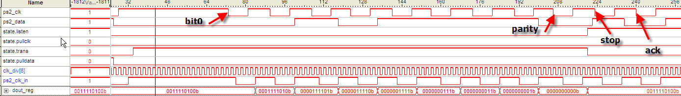
从这个图看,其实我还是分不清楚到底是下降沿,还是上升沿采样。
总结一下,主要的问题是:
1.协议一定要弄清楚,这点,外国人一点儿都不大方,原始资料不好找。
2.多看几个版本,从中找到异同,详加互参,往往能得到一点儿真知灼见。
3.跨时钟信号处理要谨慎,刚开始没有对ps2_clk做处理,直接用它的下降沿移位,读取的数据时有错误,按鼠标左键,右键的灯也会闪。
最后附上我非常粗糙的代码,作为原始版本保留吧。
library ieee;
use ieee.std_logic_1164.all;
use ieee.std_logic_unsigned.all;
use ieee.std_logic_arith.all;
entity ps2 is
port(clkin,rst :in std_logic;
ps2_clk,ps2_data :inout std_logic;
lefbut,rigbut,midbut:out std_logic;
x_mov1,x_mov2,y_mov1,y_mov2 :out std_logic_vector(6 downto 0));
end entity;
architecture behav of ps2 is
—
signal byte_cnt,delay :std_logic_vector(3 downto 0);
signal lef_latch,rig_latch,mid_latch :std_logic;
signal x_latch,y_latch :std_logic_vector(7 downto 0);
signal ps2_clk_in,ps2_clk_out,ps2_data_in,ps2_data_out :std_logic;
signal shift_reg :std_logic_vector(32 downto 0);
signal clk_div :std_logic_vector(8 downto 0);
signal clk,ce,de :std_logic;
signal dout_reg :std_logic_vector(9 downto 0);
signal cnt :std_logic_vector(7 downto 0);
constant enable_data :std_logic_vector(9 downto 0):=”0011110100″;
signal counter :std_logic_vector(1 downto 0);
signal ct :std_logic_vector(5 downto 0);
—
signal ps2_clk_syn0,ps2_clk_syn1,ps2_dat_syn0,ps2_dat_syn1,dout_syn1,dout_syn0 :std_logic;
–type define
type st is (listen,pullclk,pulldata,stablize,trans);
signal state :st ;
component SEG7_LUT is
port(oSEG :out std_logic_vector(6 downto 0);
iDIG :in std_logic_vector(3 downto 0));
end component;
begin
U1: SEG7_LUT port map(oSEG=>x_mov1,iDIG=>x_latch(3 downto 0));
U2: SEG7_LUT port map(oSEG=>x_mov2,iDIG=>x_latch(7 downto 4));
U3: SEG7_LUT port map(oSEG=>y_mov1,iDIG=>y_latch(3 downto 0));
U4: SEG7_LUT port map(oSEG=>y_mov2,iDIG=>y_latch(7 downto 4));
–clk_div,50MHz to 97.65625KHz;
process
begin
wait until clkin=’1′;
clk_div<=clk_div+1;
end process;
clk<=clk_div(8);
–sampling frame data;
process(ps2_clk_in,state)
begin
if state=listen then
if ps2_clk_in’event and ps2_clk_in=’0′ then
shift_reg(31 downto 0)<=shift_reg(32 downto 1);
shift_reg(32)<=ps2_data_in;
end if;
end if;
end process;
—
process(ps2_clk_in,cnt,state)
begin
if cnt=”11111111″ then
ct<=(others=>’0′);
elsif state=listen then
if rising_edge(ps2_clk_in) then
ct<=ct+1;
end if;
end if;
end process;
—idle state detect;
process(clk)
begin
if clk’event and clk=’1′ then
if (ps2_data_in=’1′ and ps2_clk_in=’1′) then
cnt<=cnt+1;
else
cnt<=(others=>’0′);
end if;
end if;
end process;
—-
—-
process(clk)
begin
if clk’event and clk=’1′ then
if cnt=”00001110″ and (ct(5)=’1’or ct(4)=’1′) then
lef_latch<=shift_reg(1);
rig_latch<=shift_reg(2);
mid_latch<=shift_reg(3);
x_latch<=conv_integer(x_latch)+shift_reg(19 downto 12);
y_latch<=conv_integer(y_latch)+shift_reg(30 downto 23);
end if;
end if;
end process;
lefbut<=lef_latch;
rigbut<=rig_latch;
midbut<=mid_latch;
—
ps2_clk_syn0<=ps2_clk;
ps2_dat_syn0<=ps2_data;
–tristate output for ps2_clk and ps2_data;
process(ps2_clk,ce,ps2_clk_out)
begin
if ce=’1′ then
ps2_clk<=ps2_clk_out;
else
ps2_clk<=’Z’;
end if;
end process;
–data;
process(ps2_data,de,ps2_data_out)
begin
if de=’1′ then
ps2_data<=ps2_data_out;
else
ps2_data<=’Z’;
end if;
end process;
–synchronize
process
begin
wait until clk=’1′;
–dout_syn1<=dout_syn0;
–ps2_data_out<=dout_syn1;
ps2_clk_syn1<=ps2_clk_syn0;
ps2_dat_syn1<=ps2_dat_syn0;
ps2_clk_in<=ps2_clk_syn1;
ps2_data_in<=ps2_dat_syn1;
end process;
–tranceive 0xF4 to device ,enables data transfer.
process(clk)
begin
if clk’event and clk=’1′ then
case state is
when listen => if rst=’0′ and cnt=”11111111″ then state<=pullclk;
end if;
ce<=’0′;de<=’0′;
when pullclk => if delay=”1100″ then state<=pulldata;
end if;
ce<=’1′;de<=’0′;
when pulldata=> state<=stablize;
ce<=’1′;de<=’0′;
when stablize=> if counter=”11″ then state<=trans;
end if;
ce<=’0′;de<=’1′;
when trans => if byte_cnt=”1001″ then state<=listen;
end if;
ce<=’0′;de<=’1′;
when others => state<=listen;
end case;
end if;
end process;
–pull clk low for 100us
process(clk,state)
begin
if state=pullclk then
if clk’event and clk=’1′ then
delay<=delay+1;
end if;
else
delay<=(others=>’0′);
end if;
end process;
–wait
process(clk,state)
begin
if state=stablize then
if clk’event and clk=’1′ then
counter<=counter+1;
end if;
else
counter<=(others=>’0′);
end if;
end process;
–tranceive data;adds up byte
process(ps2_clk_in,state)
begin
if state=trans then
if ps2_clk_in’event and ps2_clk_in=’1′ then
dout_reg<=’0’&dout_reg(9 downto 1);
byte_cnt<=byte_cnt+1;
end if;
else
dout_reg<=enable_data;
byte_cnt<=(others=>’0′);
end if;
end process;
—
—
ps2_data_out<=dout_reg(0);
ps2_clk_out<=’0′;
—
end behav;