My original intention (but who cares about that, anyway?)
Originally I looked for a very low noise balanced preamplifierfor dynamic microphones, but with a gain of 20 dB only. Very lownoise was meant to be 1.5 nV/Sqr(Hz) or less. I thought thisshould be easy as usual ICs like the INA103 provide as low as1.0 nV/Sqr(Hz) voltage noise. But I was wrong.
Why do low-gain amplifiers produce more noise than a high-gainones?This is for two reasons: The current noise of the input stageand the voltage noise of the feedback resister network. Have alook at the following circuit diagram:
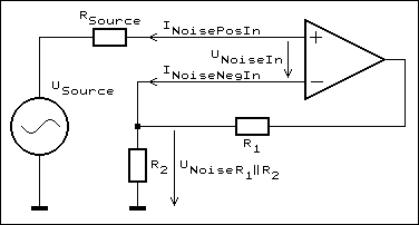
The overall amplifier noise is summed up from the followingsources:
– The input voltage noise of the Amplifier(UNoiseIn)
– The positive input current noise multipliedby the impedance of the signal source (RSource x INoisePosIn)
– The negative input current noise multipliedby the source resistance of the feedback resistor divider ((R1parallel to R2) x INoiseNegIn)
– The resistor noise of of the feedback resistordivider (R1 parallel to R2)
Of course the resistance of signal source, e. g. the microphone,adds another noise, but we can’t influence that with the designof the amplifier so I don’t include it here. My goal is the designof a preamplifier that adds so few noise to the signal that thenoise caused by the preamplifier compared to the signal source’snoise is really negligible. You should know that summing noisephysically is and mathematically must be done by summing the squareof the individual noise voltages and afterwards extracting theroot from this sum:
UNoiseSum = Sqr(UNoise12 + UNoise22 + UNoise32 +… + UNoiseN2)
The noise of a 200 Ω resistor amounts to 1.82 nV/Sqr(Hz).Should the preamplifier produce another 1.0 nV/Sqr(Hz), the sumwould become 2.08 nV/Sqr(Hz), i. e. approx. 1 dB morethan the source. My goal of 1.5 nV/Sqr(Hz) was “moderate”.
When you look at the INA103 you’ll find the current noise specifiedfor its signal inputs (INoisePosIn) there, but notfor the feedback inputs (INoiseNegIn). In fact, asthe feedback inputs are the emitters of the input transistors,the input current noise there is significantly higher that thaton the signal inputs, which are the transistor’s bases. The problem,particularly for low gains, occurs at these feedback inputs.
The INA103 provides feedback resistors of 3 kΩ ateach side (R1 in the circuit above). You cannot reducethem, the op-amp won’t work, either because the driver capacitanceis too low or the system gets instable. You have to use them.For a gain of 10 you need 2 x 333 Ω (or 1 x 333 Ω,R2 in the circuit above) to set a gain of 10. Thisresistor network produces 3.15 nV/Sqr(Hz) of voltage noiseand even more caused by the (unspecified) current noise of theINA103. The sum is 5 nV/Sqr(Hz) approx. – far, far away from mygoal and drastically reducing the system’s noise performance.
So what can be done to reduce the input noise?The feedback resistor divider’s output resistance must drasticallybe reduced. It is, by the way, drastically lower when the gainis high, i. e. it is 6 Ω only in case the gain is 1000(60 dB). But for low gains it is difficult to reduce. Justimagine a gain of 2 and a feedback resistance of 6 Ω:The divider in the circuit above ought to built from two 12 Ωresistors! The input power for this divider would be 4 Win case of an output voltage of 10 Vrms, whichis not an unusual voltage in average amplifier stages.
I did not want to go that far, but a power output stage sufficientto drive 100 Ω dividers (90 + 10 Ω)should be aimed.
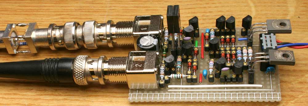
I finally ended in a fully discrete circuit with a very highopen-loop gain and an appropriate power output stage. I made lotsof experiments, experiences and measurements for lowest noisetransistors. Particularly measuring these small voltages and currentsreliably and to make these measurements reproducible is reallydifficult and sometimes almost drove me mad.
My ultra-low noise preamplifier circuitThe circuit diagram below shows my prototype, an unbalancedamplifier with a gain of 1000 built for experiments and for noisemeasurements. It is, so to speak, one half of the INA103 inputstage. I was disappointed to realize that it was not possibleto reduce it’s gain down to 10. I had expected that I only hadto increase C4 sufficiently, but the system shows relaxationoscillations. I am convinced that the huge open loop gain hasto be reduced to avoid that.
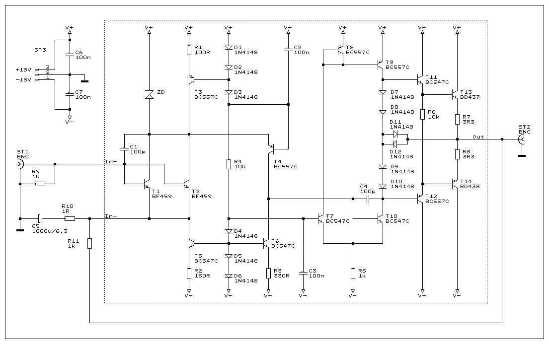
Transistor SelectionThe noise performance, on the other hand is much better thanI originally aimed. Currently the input voltage noise isas low as 0.45 nV/Sqr(Hz), or, for a balanced version, itwould be 0.64 nV/Sqr(Hz). I tested a couple of transistors.The best ones all were high-voltage power transistors. My favoritesup now are BF459 or MJE13007. BF459 is better when current noisematters, i. e. impedances like dynamic microphones and low gains.MJE13007 produces less voltage noise, but much more current noiseand is better for low-impedance sources like ribbon microphonesand high gains.
I cannot explain why these transistors are good and othersnot. Some say it’s the base resistance that matters, but I believethis is not the whole truth. (Electronics, to my point of view,should not be a matter of believing, but I’m not a semiconductorphysician and what shall I do as long as I do not know. I wouldhighly appreciate everybody giving me an exact explanation.) Highercollector currents, up to a certain limit, reduce the input voltagenoise, but increase the input current noise(s). Depending on thesource resistance a specific collector current is optimal.
The voltage noises, measured at a collector current of 4 mAapprox. and source and feed-back resistances of 1 Ωeach are:
Single BF459 0.54 nV/Sqr(Hz) Dual BF459 0.45 nV/Sqr(Hz) Single MJE13007 0.38 nV/Sqr(Hz)
Theoretically an improvement of 3 dB could be expectedusing two transistors in parallel, each with the same collectorcurrent as the single one, but practically, if at all, it is muchless. This obviously is caused by comparably high noise currentsthrough the source and feed-back resistances. There was no improvementwith two MJE13007 in parallel. Instead, at low frequencies thenoise was slightly increased, a typical effect of current noise.I did not investigate that further. Instead, I would rather testseveral more transistors, as those few I happened to have wereso different from each other that it is very likely to find significantlybetter ones.
As an example, here are the noise measured spectra of a fewmeasurements:
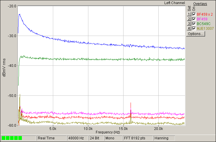
From bottom to top:
Brown: MJE13007
Red: Two BF459 in parallel
Pink: BF459
Green: BC549C, a “low-noise”, low power transistor,for comparison
Blue: Two BF459 in parallel, 1 kΩ as source resistance
In the latter spectrum the 1/f base-current noise is obvious.It can be calculated as 1.5 pA/Sqr(Hz) approx. @ 2 mA collectorcurrent through each transistor.
Further transistors I tested:
BD237, BD437, TIP152, BF471, MJE340 and several low and mediumpower transistors. Next best to the BF459 is the MJE340, whichwas my favorite until I tested the BF459.
Better do not build this circuit…… unless you are not able to discriminate by smell if a transistoror a resistor is about to get hot!
This is an experimental circuit. It rather should not be usedin practice as it shows some problems that should not occur. E.g., small input voltages of some 10 or few 100 mV are sufficientto destroy the circuit because the input transistor’s collectorcurrent can cause high reverse currents through the emitter ofT4 and destroy it. I did not test the zener diode ZDabove proposed in the circuit diagram above which might help.Also, I sometimes observed the circuit falling into an oscillatingstate. I did not investigate this further, it did not happen often.Both problems should not occur when a source is fixed (not plugged)to the input. But as I said, the more harm- than useful huge openloop gain should be reduced anyway.
For a more precise gain and lower low frequency limit I recommendto use an OSCON 2700 µF/2.5 V from Sanyoas electrolytic capacitor C5, which is as small asthe standard one I used in my prototype but has 1/10thof its ESR (10 instead of 100 mΩ).
This project is experimental. Should you work on somethingwhere it might be interesting, i. e. on microphones, or shouldit be interesting for you anyhow else, I’d appreciate your feed-back.So you are very welcome to emailme!
Source Adress:http://www.beis.de/Elektronik/LNPreAmp/LNPreAmp.html